> Infrastructure involved: HP V1910 (x2), Synology NAS (x3), TrueNAS, Windows Server 2022 (Hyper-V)
LACP (Link Aggregation Control Protocol), defined by the IEEE 802.3ad standard (part of 802.1AX), allows multiple physical links to be grouped into a single logical link called a LAG (Link Aggregation Group). There are numerous benefits:
- Increased aggregate bandwidth for multiple traffic flows
- Automatic redundancy: if a physical link fails, the others take over without intervention
- Dynamic negotiation: the protocol detects and adapts to changes in link status
> ⚠️ Important: LACP does not increase the throughput of a single flow. A given flow always remains on the same physical link (hashing). The benefit is realized across multiple simultaneous flows.
Background and Terminology
First and foremost, it is essential to clarify the terminology used by different manufacturers, which is a frequent source of confusion:
| Manufacturer | Link Aggregation | 802.1q Tagged Link |
|---|---|---|
| Cisco | port-channel / trunk |
trunk |
| Classic HP Procurve | trunk |
tagged port |
| HP V1910 (Comware/H3C) | Bridge-Aggregation (BAGG) |
tagged port |
The HP V1910s are actually H3C OEM switches (following HP’s acquisition of 3Com’s networking division). Their firmware is based on Comware, not on genuine Procurve firmware. The interface and CLI are radically different from a classic Procurve.
The main pitfall of the V1910: dual LACP configuration
This is the mistake everyone makes, and the reason why LACP never comes up via the graphical interface.
On Comware, LACP configuration must be applied at two levels:
- On the Bridge-Aggregation interface: set the mode to dynamic
- On each member port individually: confirm membership in the group
> ⚠️ Counterintuitive behavior: this is the opposite of VLANs, which are configured only on the BAGG and automatically propagate to member ports. LACP mode, however, must be explicitly confirmed on each physical port because it operates at the cable level (sending LACPDUs).
The V1910’s graphical interface configures dynamic mode on the BAGG but fails to propagate it to the member ports. Result: the ports remain in static mode, and the LAG never comes up. All LACP operations must be performed via the CLI.
Prerequisites: CLI access on the V1910
Accessing advanced configuration mode requires enabling extended CLI mode:
_cmdline-mode on
→ Confirm with Y → Password: 512900
system-view
Part 1: LACP between the two switches (inter-switch link)
Infrastructure
| Remote Switch | Local Switch | |
|---|---|---|
| LAG Ports | GE1/0/1 and GE1/0/2 | GE1/0/3 and GE1/0/4 |
| Bridge Aggregation | BA1 | BA1 |
Initial State
Both switches had a 2 Gbps link in Static mode, with several VLANs in transit.
 Bridge-Aggregation1 in Static mode on the remote switch
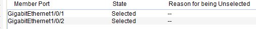 GE1/0/1 and GE1/0/2 selected on the remote switch
 Bridge-Aggregation1 in Static mode on the local switch
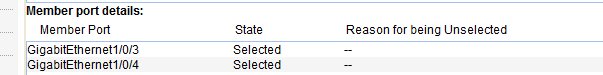 GE1/0/3 and GE1/0/4 selected on the local switch
 VLAN configuration on the Bridge-Aggregation — unchanged after migration to LACP
Migration Strategy
Since the inter-switch link is the only communication path between the two switches, the procedure must be performed in a specific order:
- Apply the configuration to the remote switch first — the connection is lost immediately
- Apply immediately to the local switch — the LAG comes back up
> ℹ️ The VLANs configured on the BAGG are preserved during the transition from static to dynamic. It is not necessary to reconfigure them.
CLI Procedure
On Comware, it is impossible to change the mode of a BAGG as long as it has member ports. You must therefore remove them, change the mode, and then add them back.
On the remote switch (FIRST):
interface GigabitEthernet 1/0/1
 undo port link-aggregation group
 quit
interface GigabitEthernet 1/0/2
 undo port link-aggregation group
 quit
interface Bridge-Aggregation 1
 link-aggregation mode dynamic
 quit
interface GigabitEthernet 1/0/1
 port link-aggregation group 1
 quit
interface GigabitEthernet 1/0/2
 port link-aggregation group 1
 quit
On the local switch (IMMEDIATELY AFTER):
interface GigabitEthernet 1/0/3
 undo port link-aggregation group
 quit
interface GigabitEthernet 1/0/4
 undo port link-aggregation group
 quit
interface Bridge-Aggregation 1
 link-aggregation mode dynamic
 quit
interface GigabitEthernet 1/0/3
 port link-aggregation group 1
 quit
interface GigabitEthernet 1/0/4
 port link-aggregation group 1
 quit
Verification
display link-aggregation verbose
 Remote switch: Bridge-Aggregation1 in Dynamic mode, 2 ports Selected, Partner ID negotiated
 Local switch: Bridge-Aggregation1 in Dynamic mode, 2 ports Selected
Expected result on each switch:
Aggregation Interface: Bridge-Aggregation1
Aggregation Mode: Dynamic
Loadsharing Type: Shar
System ID: 0x8000, xxxx-xxxx-xxxx
Local:
  Port             Status  Priority Oper-Key  Flag
  GE1/0/x          S       32768    1         {ACDEF}
  GE1/0/x          S       32768    1         {ACDEF}
Remote:
  Actor            Partner Priority Oper-Key  SystemID               Flag
  GE1/0/x          x       32768    1         0x8000, xxxx-xxxx-xxxx {ACDEF}
  GE1/0/x          x       32768    1         0x8000, xxxx-xxxx-xxxx {ACDEF}
Meaning of the {ACDEF} flags:
| Flag | Meaning |
|---|---|
| A | LACP Active |
| B | LACP Fast Timeout (present on the Synology/Linux side) |
| C | Aggregation |
| D | Synchronization |
| E | Collecting |
| F | Distributing |
| G | Defaulted (⚠️ the switch is not receiving LACPDUs) |
| H | Expired |
Part 2: LACP between Synology NAS devices and the remote switch
Infrastructure
Three Synology NAS devices connected to the remote switch, each on a dedicated Bridge-Aggregation with 2 physical ports.
Initial state of the Synology devices
The three Synology NAS devices were configured in XOR Balance mode (IEEE 802.3ad draft v1 — static).
 XOR Balance mode on Synology — equivalent to static LAG
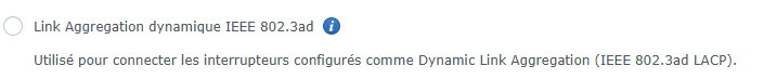 IEEE 802.3ad Dynamic Link Aggregation option available on DSM
Procedure
Order of steps:
- Change the bond on DSM to IEEE 802.3ad Dynamic Link Aggregation
- Immediately apply the CLI commands on the switch
Example for a NAS on BA4 (ports 9+10):
interface GigabitEthernet 1/0/9
 undo port link-aggregation group
 quit
interface GigabitEthernet 1/0/10
 undo port link-aggregation group
 quit
interface Bridge-Aggregation 4
 link-aggregation mode dynamic
 quit
interface GigabitEthernet 1/0/9
 port link-aggregation group 4
 quit
interface GigabitEthernet 1/0/10
 port link-aggregation group 4
 quit
Repeat for each BAGG, adjusting the port numbers.
Verification
display link-aggregation verbose
Expected result for each Synology BAGG:
Aggregation Interface: Bridge-Aggregation4
Aggregation Mode: Dynamic
Local:
  GE1/0/9          S       32768    4         {ACDEF}
  GE1/0/10         S       32768    4         {ACDEF}
Remote:
  GE1/0/9          2       255      17        0xffff, xxxx-xxxx-xxxx {ABCDEF}
  GE1/0/10         1       255      17        0xffff, xxxx-xxxx-xxxx {ABCDEF}
> ℹ️ The B flag on the Synology side is normal: DSM uses FAST mode (LACPDUs every second) while the switch is in SLOW mode (30 seconds). This timer difference is allowed by the standard.
Part 3: LACP between TrueNAS and the local switch
Infrastructure
- TrueNAS connected to a BAGG on the local switch, 2 physical ports
- Existing bond in Load Balance mode (static)
TrueNAS Configuration
In the TrueNAS interface: Network → Interfaces → Edit bond0
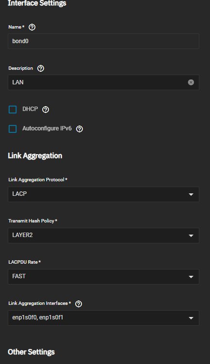 TrueNAS bond configuration: LACP, LACPDU Rate FAST, Transmit Hash Policy LAYER2
Recommended settings:
- Link Aggregation Protocol: LACP
- Transmit Hash Policy: LAYER2
- LACPDU Rate: FAST
> ⚠️ On TrueNAS, after modifying the bond, you must click Test Changes and then Save. Without this step, the configuration will not be applied.
Local Switch CLI Procedure
interface GigabitEthernet 1/0/15
 undo port link-aggregation group
 quit
interface GigabitEthernet 1/0/16
 undo port link-aggregation group
 quit
interface Bridge-Aggregation 6
 link-aggregation mode dynamic
 quit
interface GigabitEthernet 1/0/15
 port link-aggregation group 6
 quit
interface GigabitEthernet 1/0/16
 port link-aggregation group 6
 quit
> ℹ️ Since the TrueNAS management interface is not on the bond, there is no risk of losing access. The order of remote/local switch configuration is not critical here.
Part 4: LACP between Windows Server servers and the local switch
Infrastructure
Two Hyper-V hypervisors, each with two network teams: one for the management LAN, one for VM traffic.
Network Cards
The servers are equipped with Intel PRO/1000 PT Quad Port cards, which are perfectly suited for teaming.
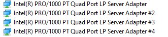 Intel PRO/1000 PT Quad Port cards
LAN TEAM: Windows LBFO NIC Teaming
The LAN teams are managed via Windows LBFO NIC Teaming.
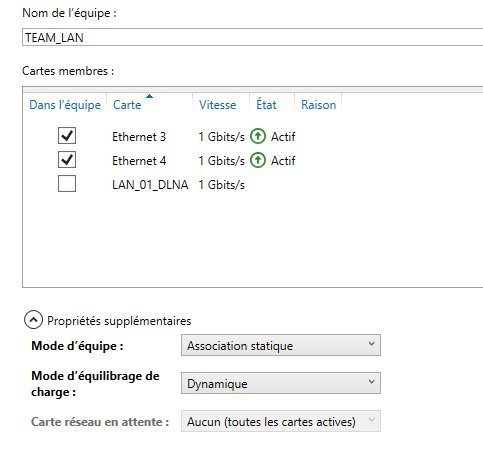 Windows NIC Teaming Manager — LAN team in Static Association before migration
PowerShell Verification:
Get-NetLbfoTeam | Format-List *
Get-NetLbfoTeamMember
Migration to LACP via PowerShell:
Set-NetLbfoTeam -Name "TEAM_LAN" -TeamingMode Lacp -LacpTimer Fast
Or via the NIC Teaming graphical manager: change the Team Mode to LACP and the Load Balancing Mode to Dynamic.
Local switch commands for the corresponding BAGG:
interface GigabitEthernet 1/0/5
 undo port link-aggregation group
 quit
interface GigabitEthernet 1/0/6
 undo port link-aggregation group
 quit
interface Bridge-Aggregation 2
 link-aggregation mode dynamic
 quit
interface GigabitEthernet 1/0/5
 port link-aggregation group 2
 quit
interface GigabitEthernet 1/0/6
 port link-aggregation group 2
 quit
VIRTUAL TEAM: LBFO SwitchIndependent
The virtual team on the PRA server (migrated Windows Server 2019) is in SwitchIndependent mode. This mode is compatible with LACP on the switch side.
Migration to LACP:
Set-NetLbfoTeam -Name "TEAM_VIRTUAL" -TeamingMode Lacp -LacpTimer Fast
Local switch commands for the corresponding BAGG:
interface GigabitEthernet 1/0/11
 undo port link-aggregation group
 quit
interface GigabitEthernet 1/0/12
 undo port link-aggregation group
 quit
interface Bridge-Aggregation 7
 link-aggregation mode dynamic
 quit
interface GigabitEthernet 1/0/11
 port link-aggregation group 7
 quit
interface GigabitEthernet 1/0/12
 port link-aggregation group 7
 quit
Special Case: Hyper-V vSwitch on Windows Server 2022 (SET)
The Hyper-V vSwitch on the production server (fresh Windows Server 2022 installation) uses Switch Embedded Teaming (SET), not LBFO.
Why SET and not LBFO?
Microsoft has deprecated LBFO on new Windows Server 2022 installations. Creating an LBFO team is either denied or strongly discouraged. SET is the official replacement, but it has a major limitation: SET does not support LACP. It operates only in static/SwitchIndependent mode in the Hyper-V context.
> ℹ️ On the PRA server (Windows Server 2019 migrated from a previous installation), LBFO existed prior to migration and was retained by Windows. This is why LBFO works on this server but not on the fresh 2022 installation.
Consequence: the BAGG corresponding to the vSwitch remains in Static mode. Attempting to switch it to LACP would cause the link to fail.
Verifying SET load balancing from the switch:
display interface GigabitEthernet 1/0/7
display interface GigabitEthernet 1/0/8
The traffic counters on both ports confirm that SET is properly distributing VM traffic across the two physical links. Windows statistics cannot be used for this verification because SET hides the physical member cards from the operating system.
Saving the configuration
> ⚠️ Critical: without this command, the entire configuration will be lost on the next reboot.
On each switch after every change:
save force
Final Summary
| Device | Mode |
|---|---|
| Inter-switch link | ✅ LACP Dynamic |
| Synology NAS x3 | ✅ LACP Dynamic |
| TrueNAS | ✅ LACP Dynamic |
| Windows servers — TEAM LAN | ✅ LACP Dynamic |
| PRA server — TEAM VIRTUAL | ✅ LACP Dynamic |
| Production Server — Hyper-V vSwitch (SET) | ⚠️ Static (Windows Server 2022 limitation) |
The complete migration of the infrastructure to Dynamic LACP is complete, with the exception of the production server’s Hyper-V vSwitch, which is constrained by SET limitations on Windows Server 2022.
Key points of this migration:
- The V1910 GUI is insufficient for configuring LACP — use the CLI exclusively
- On Comware, LACP mode must be configured at two levels: BAGG and individual member ports
- VLANs are preserved during the transition from static to dynamic; no need to reconfigure them
- LBFO is deprecated on Windows Server 2022 — new installations use SET, which is incompatible with LACP
- TrueNAS requires a "Test Changes" before saving; otherwise, the configuration is not applied
- The LACP throughput gain is visible on multiple streams, not on a single stream