While digging through my archives for the previous article on the M2 SSD, I came across this:
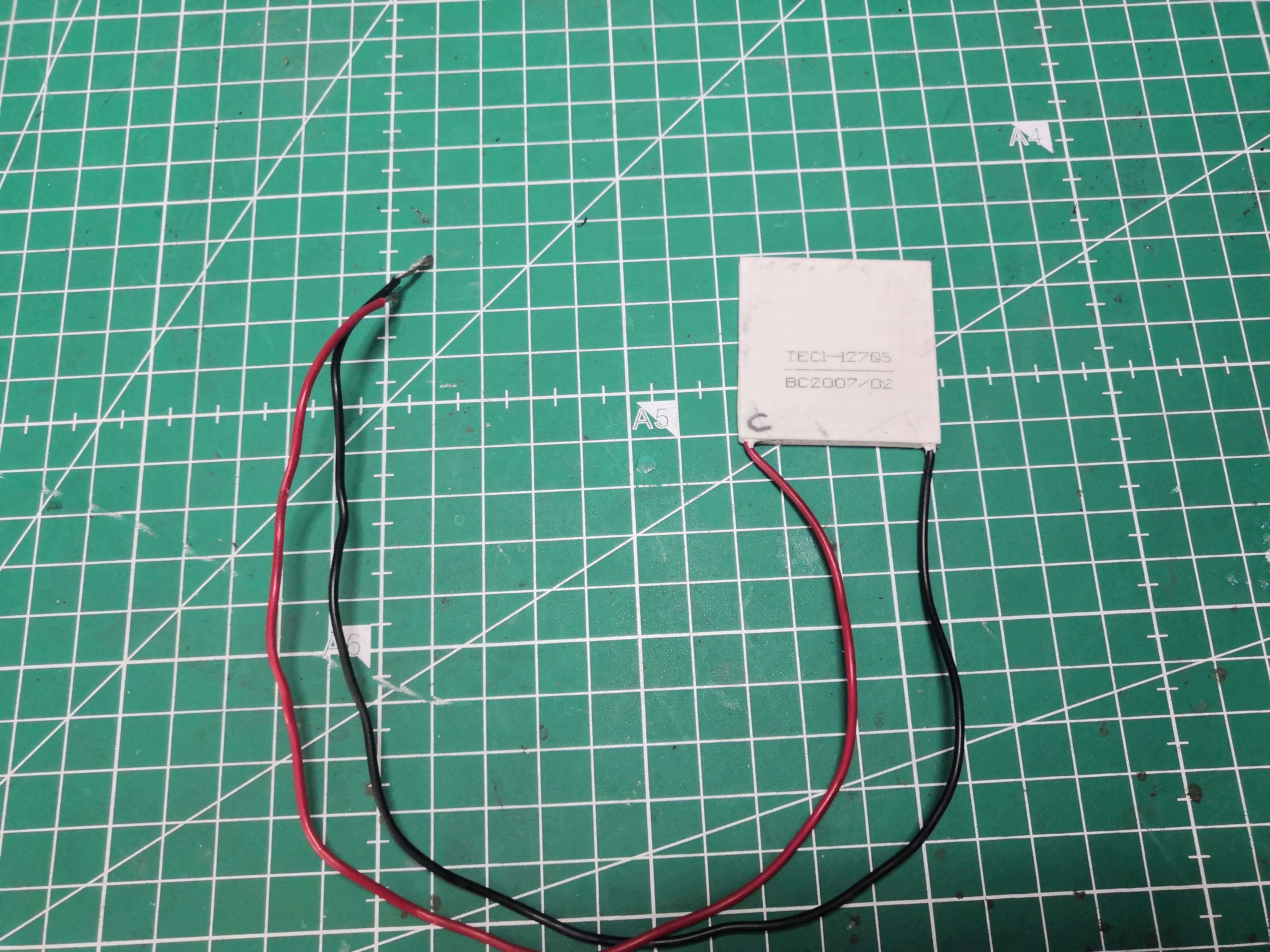
A TEC1-12705 cell salvaged from an old 12V cooler, the kind you put in the trunk of a car. I salvaged this cell 3 or 4 years ago, carefully stored it in a drawer, and never tested it.
Back in the 2000s, Peltier cells on CPUs were the Holy Grail. Overclocking forums talked about them like they were a trade secret. A few well-equipped geeks used them, and the photos made everyone drool. Back then, I would have sold my soul to get one.
In 2026, I finally ran the test I’d never been able to do. Except now I know in advance that it won’t work. But I’m going to do it anyway.
You would have done the same… well, not so sure.
What is a Peltier cell?
A Peltier cell—or TEC for Thermoelectric Cooler—is a semiconductor component that, when a direct current is passed through it, pumps heat from one side to the other. One side cools down, the other heats up. No moving parts, no liquid, nothing. Just electrons doing the work.
The TEC1-12705 we’ve sourced here is a 40×40mm, 12V, 5A, 60W unit. Its theoretical cooling capacity: approximately 57W. Its maximum temperature difference at no load: 68°C.
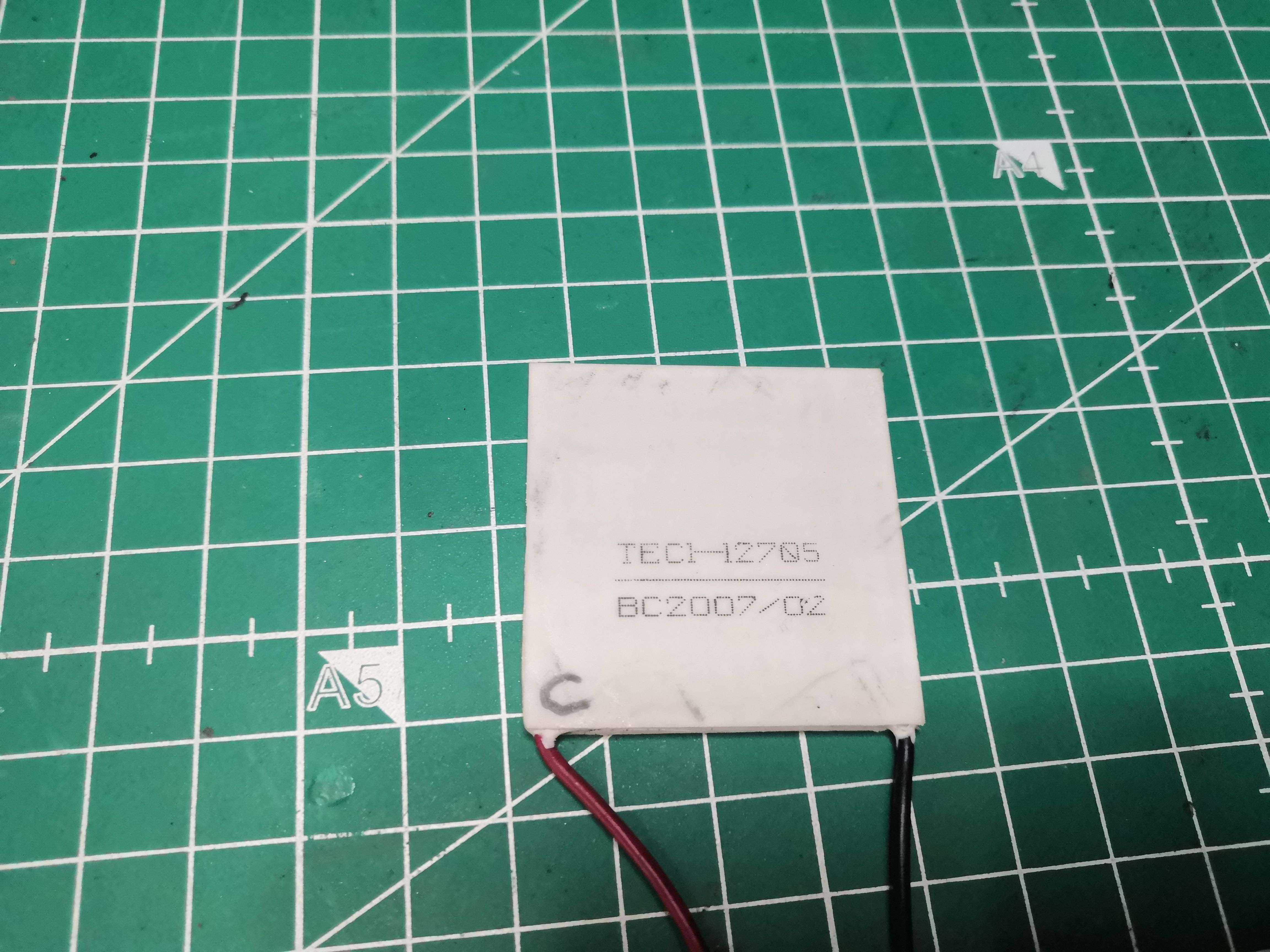
A useful note before we go any further: the printed side isn’t necessarily the cold side. Manufacturers don’t follow any conventions. The only reliable method is to power it up and put your finger on it. And Ouch… that hurts. The printed side was the hot side—now I’ve marked it “C” with a permanent marker, and the smooth side is the cold side marked “F.” Fire burns, and water wets…
The Test Subject
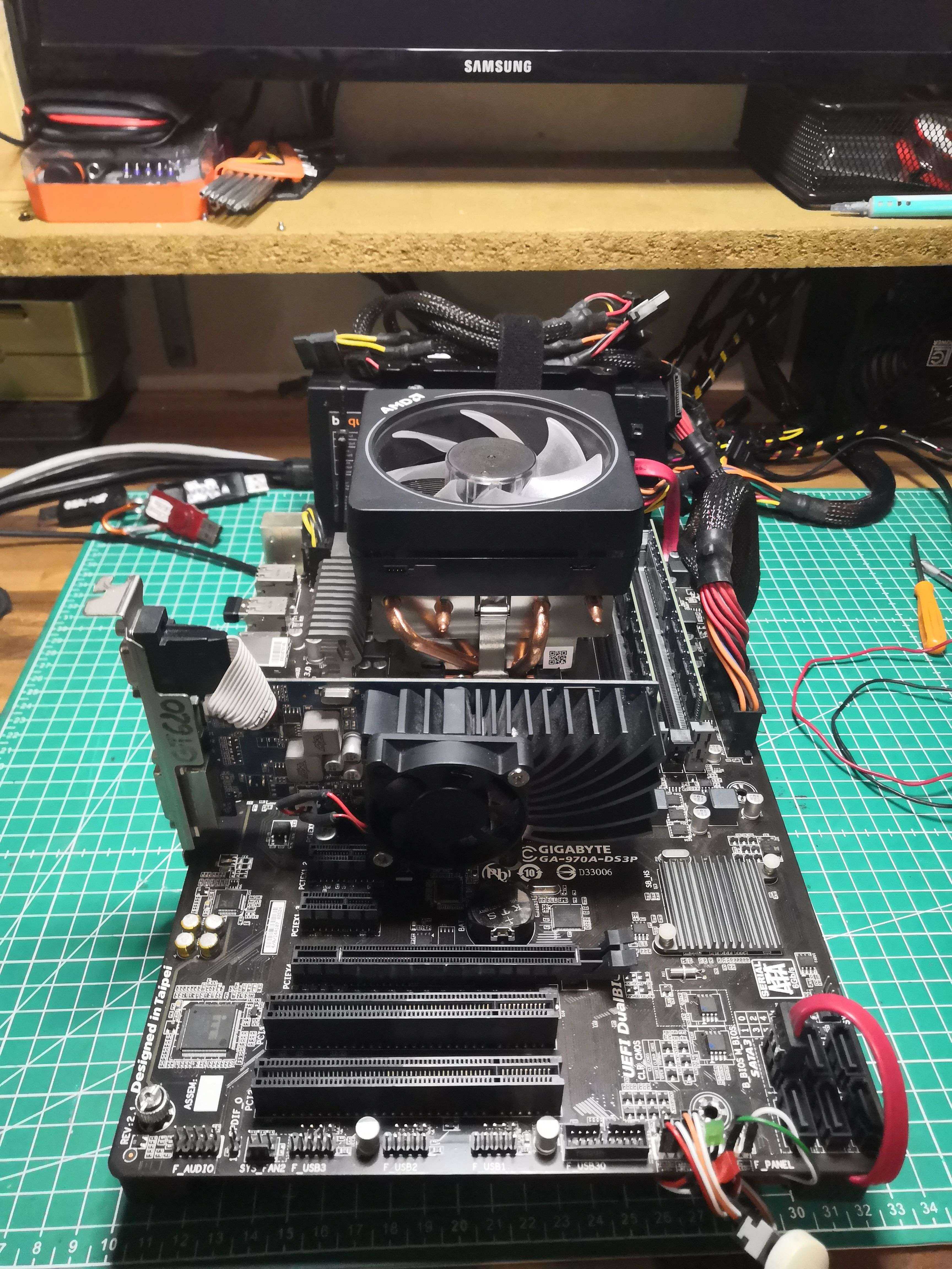
The test bench for the experiment, a motherboard mounted on aluminum rails:
| Component | Details |
|---|---|
| CPU | AMD FX-6300 Six-Core — 3.5GHz base, 32nm Piledriver |
| TDP | 95W |
| Socket | AM3r2 |
| Motherboard | Gigabyte GA-970A-DS3P |
| RAM | 2×4GB DDR3 1600 MHz |
| GPU | ASUS GeForce GT 620 |
| Storage | 120GB SATA SSD |
| OS | Windows 11 Pro 23H2 |
The FX-6300 is running here slightly overclocked at 4.4GHz (+900MHz above the base frequency) with a Vcore of 1.296V measured under load. For cooling, an AMD Wraith Prism 140W TDP cooler compatible with Ryzen 7
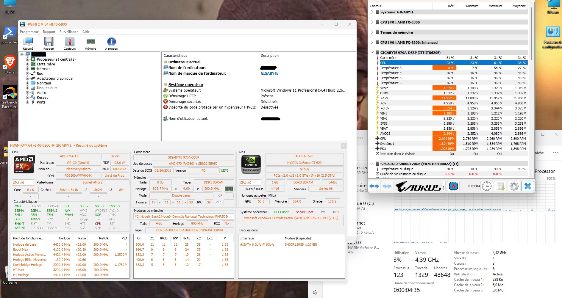
The baseline before any modifications:
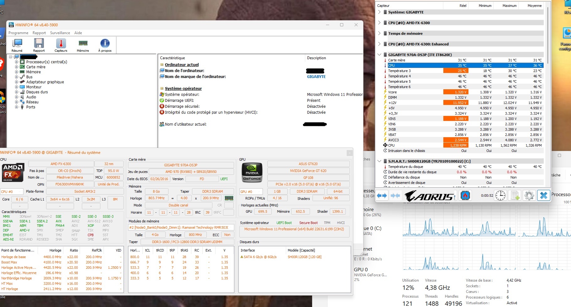 35°C idle at 4.4GHz — this is our baseline
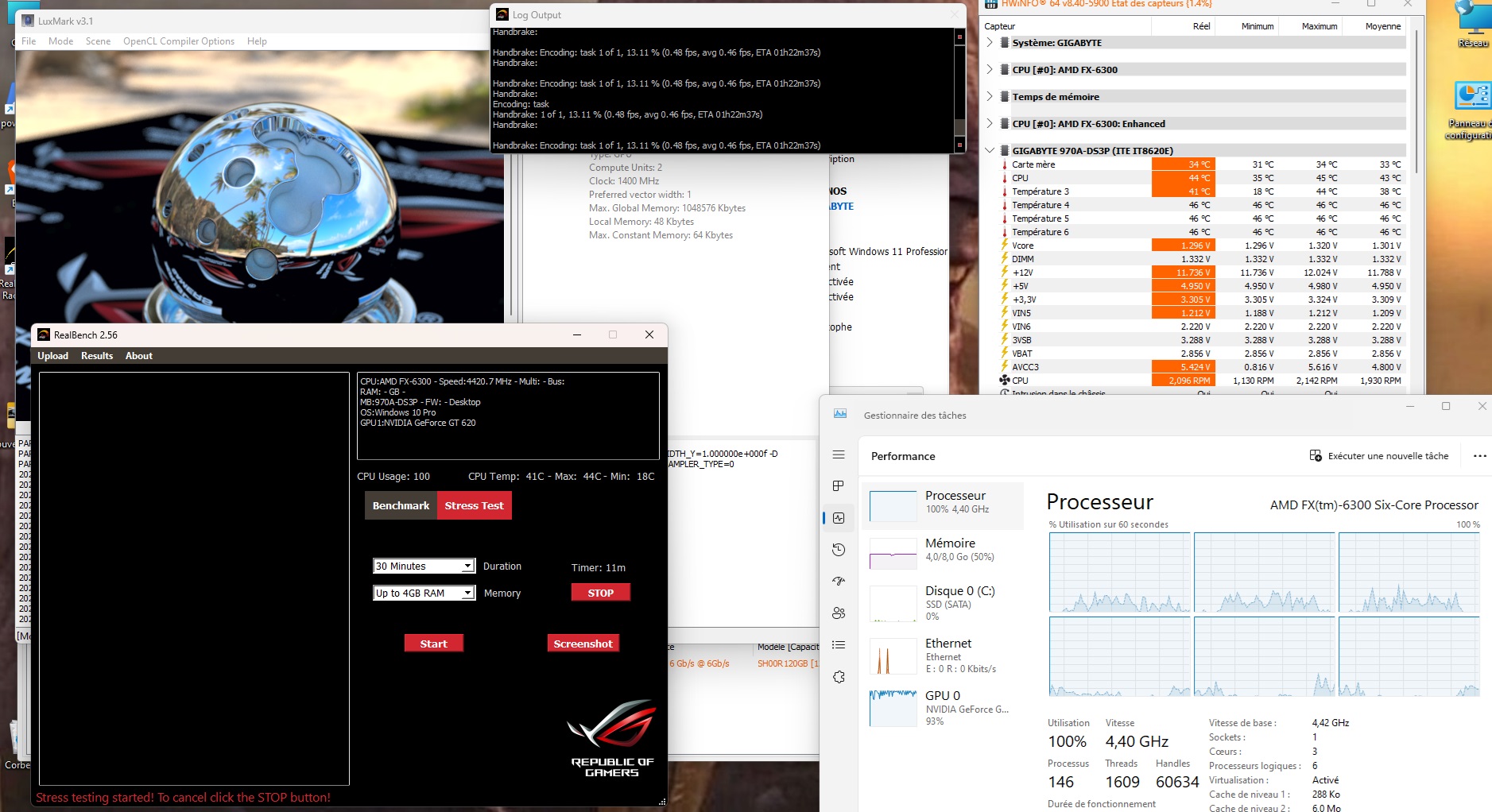 44°C under full RealBench load — for basic hardware, that’s decent
The setup: washers and thermal paste
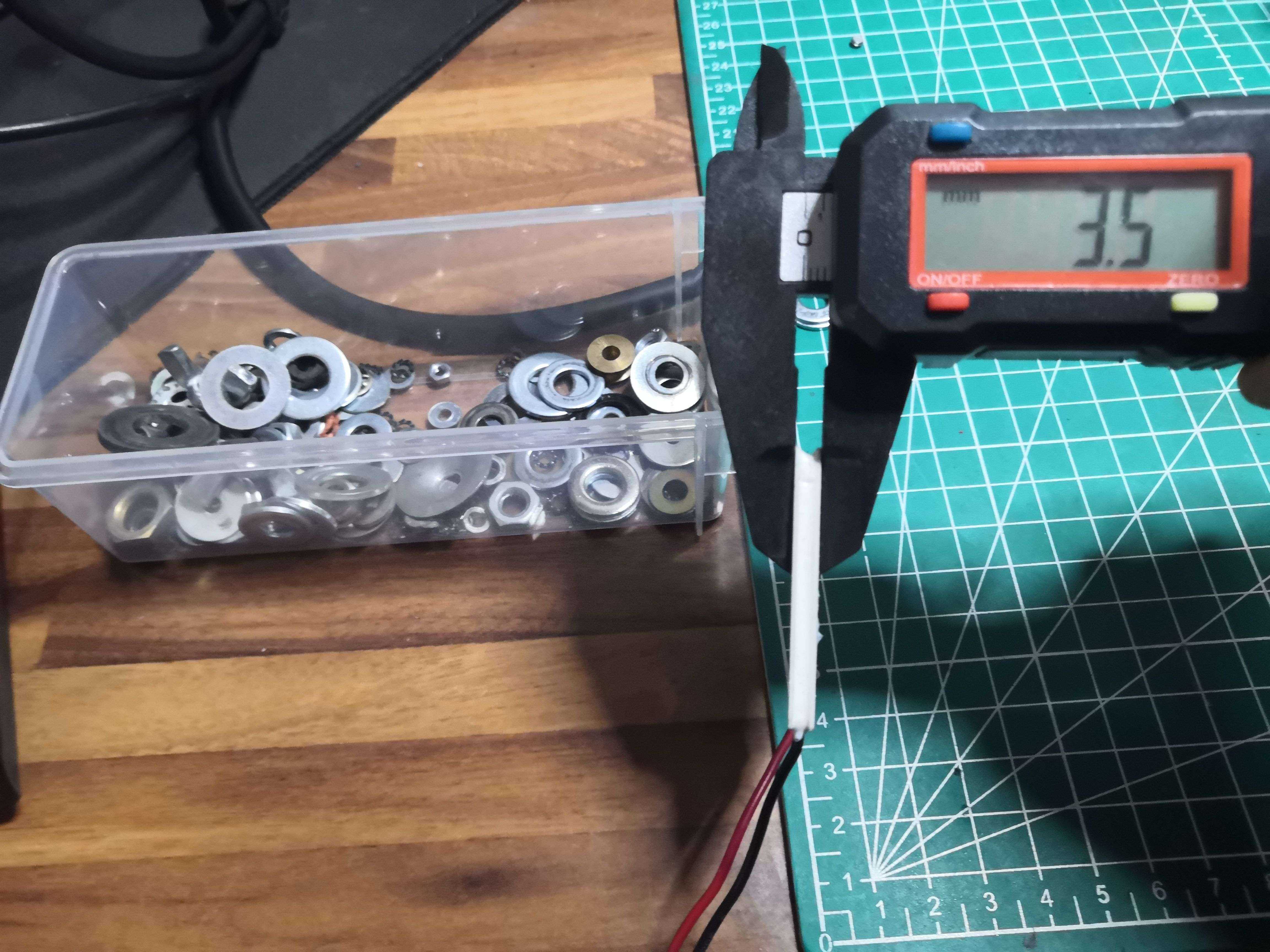
The cell is 3.5mm thick — measured with a caliper, because here we measure, we don’t guess. The heatsink is designed to press directly against the IHS, not against a 4mm ceramic plate. Solution: recycled washers to make up the height and maintain proper pressure.
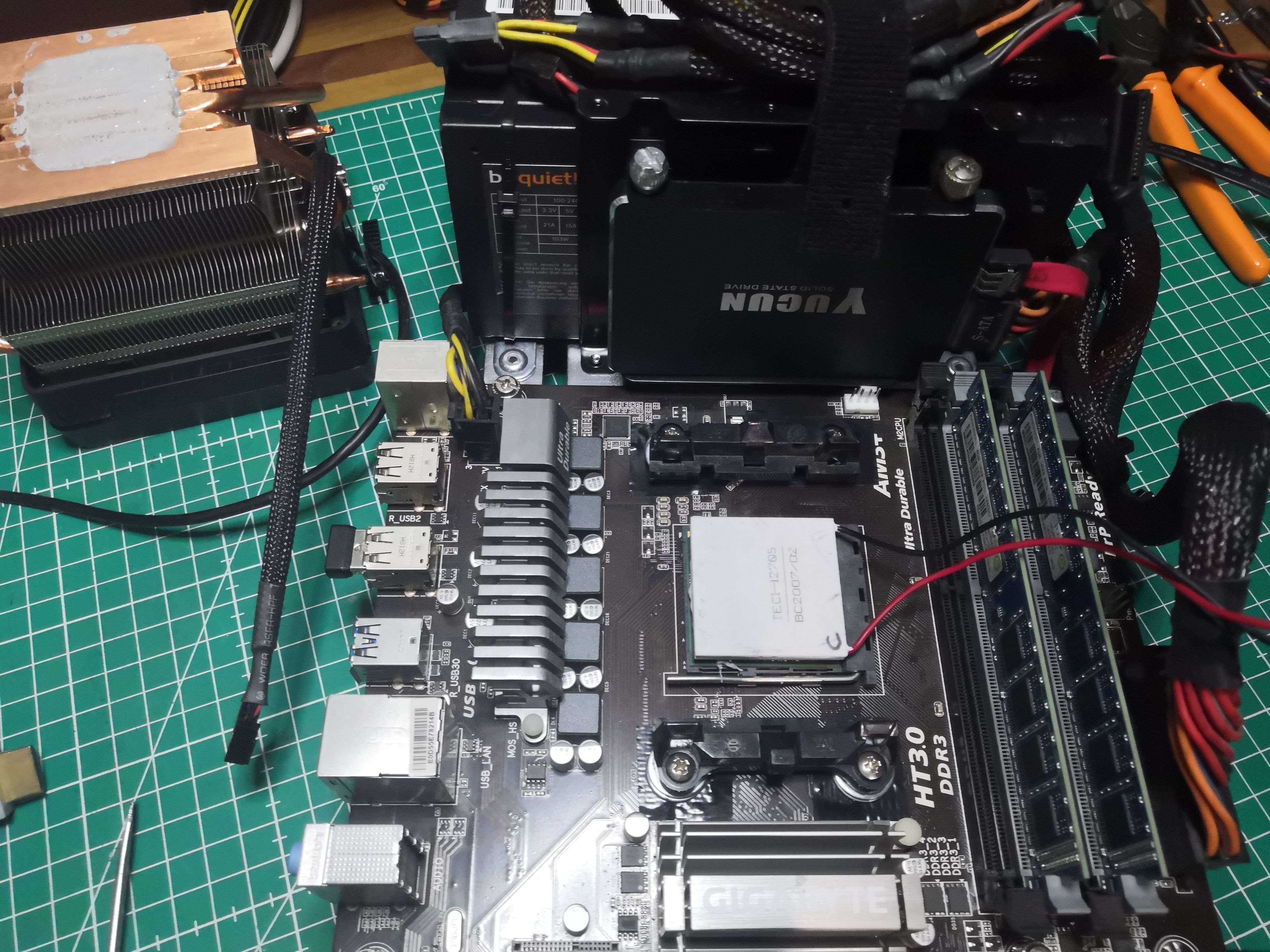 The cell in place on the IHS — cold side (F) against the CPU, hot side (C) toward the heatsink
The sandwich principle, in order:
CPU IHS
    ↓  thermal paste
 Cold side of the Peltier (F)
 Hot side of the Peltier (C)
    ↓  thermal paste
  Heat sink + fan(s)
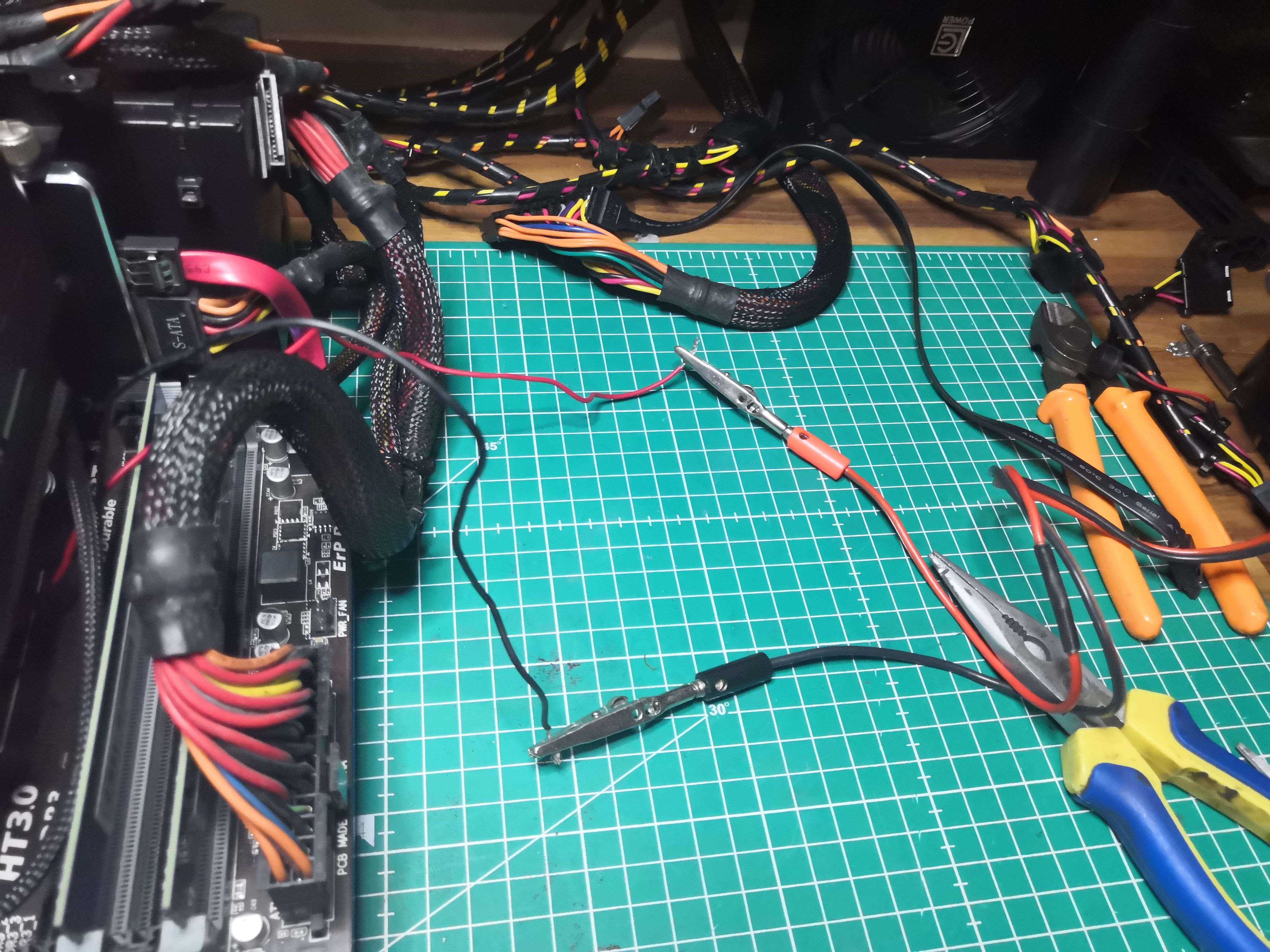
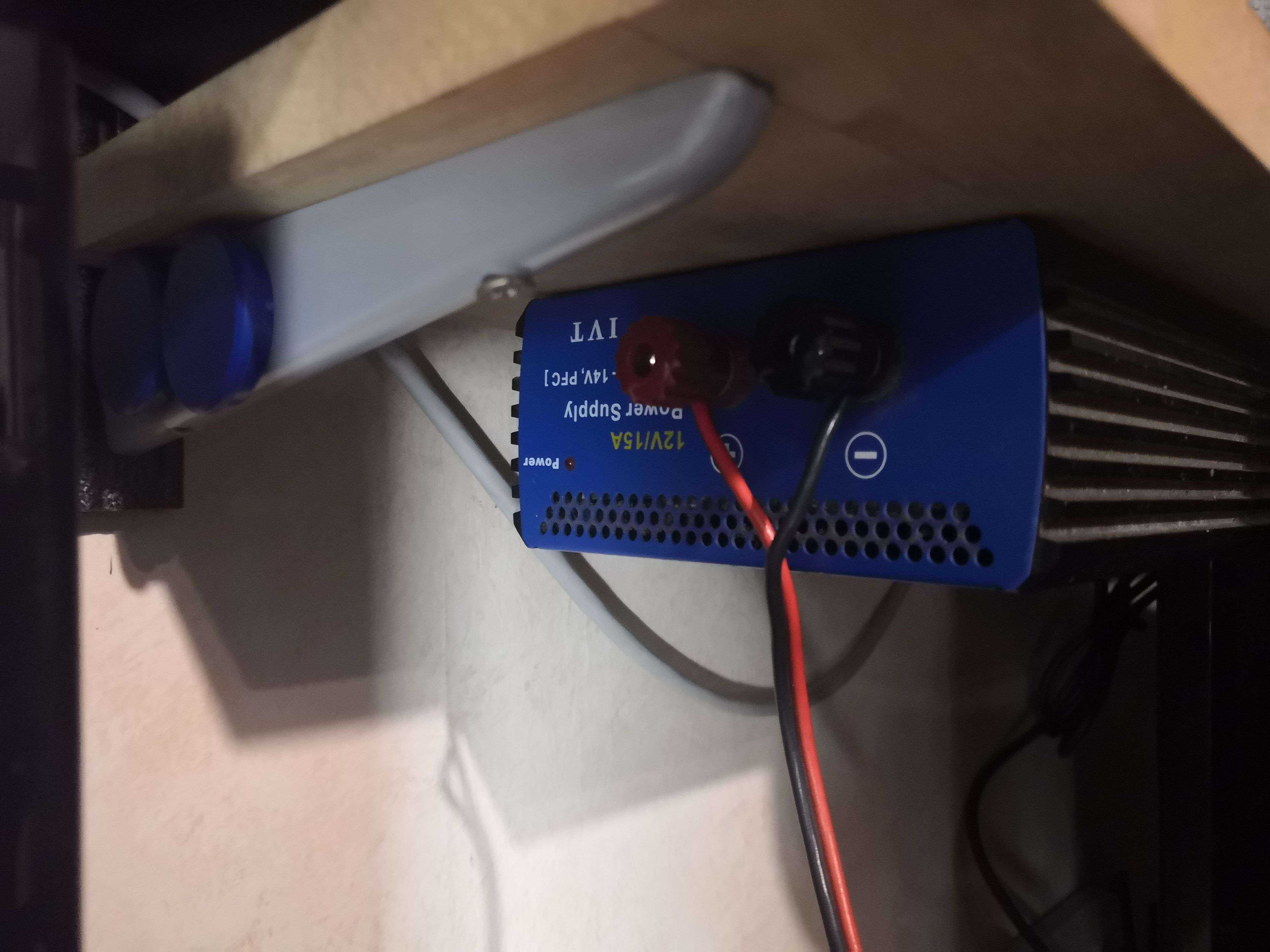
The Peltier is powered by a separate 12V/15A IVT power supply mounted under a shelf in the workshop — we’re not going to draw an additional 5A from the motherboard’s power rails.
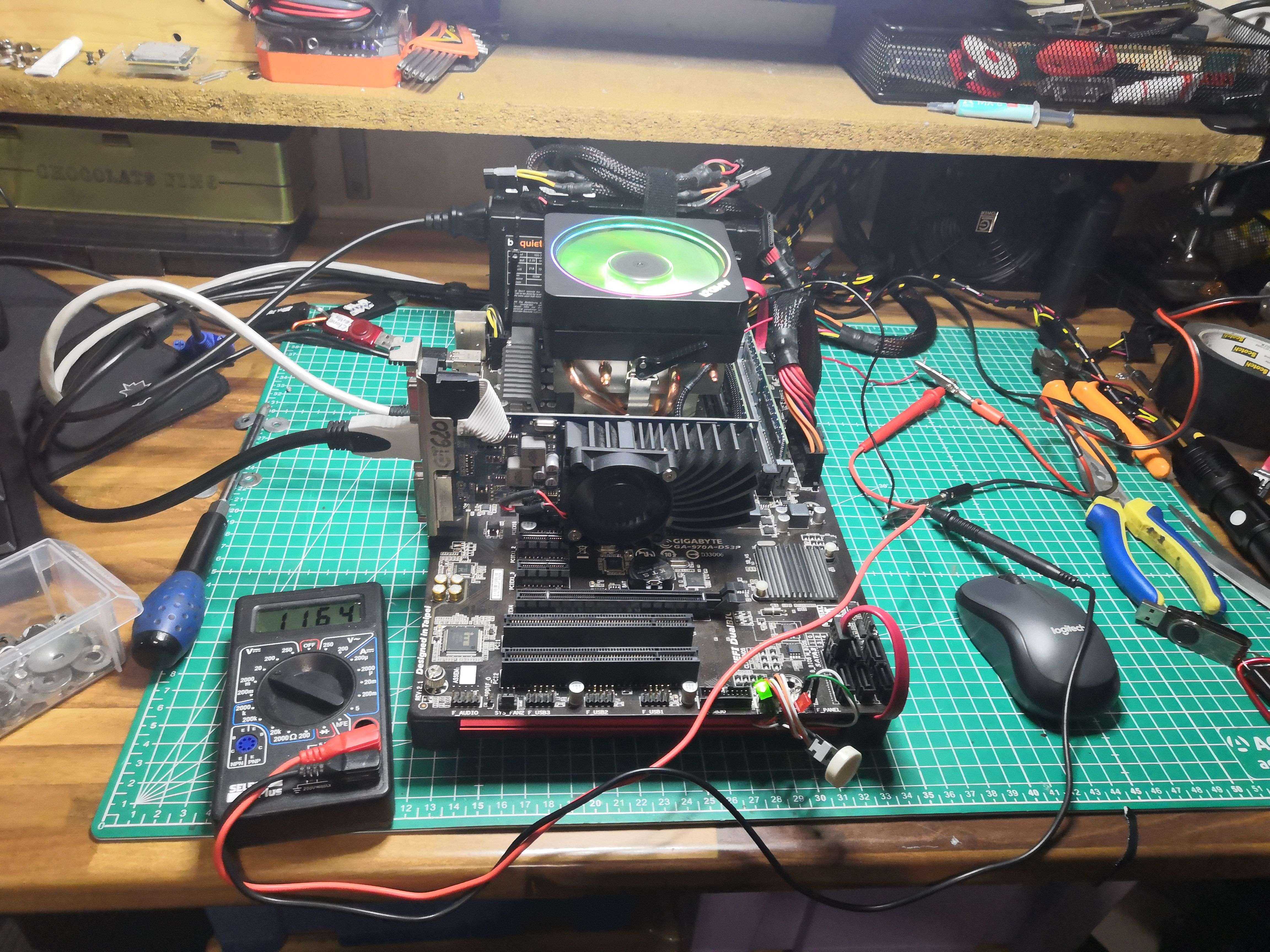 The complete bench in action — the multimeter checks the Peltier’s supply voltage
Before we begin: the theory that shatters the dream
A brief physics aside to help understand why things are going to go wrong.
The Peltier has a coefficient of performance (COP) that measures its efficiency: it is the ratio of heat removed on the cold side to the electrical power consumed. On our TEC1-12705 at full load:
- Power consumption: 60W
- Heat removed on the cold side: ~30 to 40W
- Total heat rejected on the hot side: ~90 to 100W
In other words, to cool the CPU, the heatsink must dissipate the heat from the CPU AND the 60W consumed by the Peltier. With a CPU at 95–100W at 4.4GHz, that’s ~160W total to be dissipated by a heatsink rated for 140W.
The laws of physics were against me from the start. That didn’t stop me from doing it anyway.
The results: hope, then collapse
At idle, it looks good
 Already -12°C at idle at the same frequency — promising
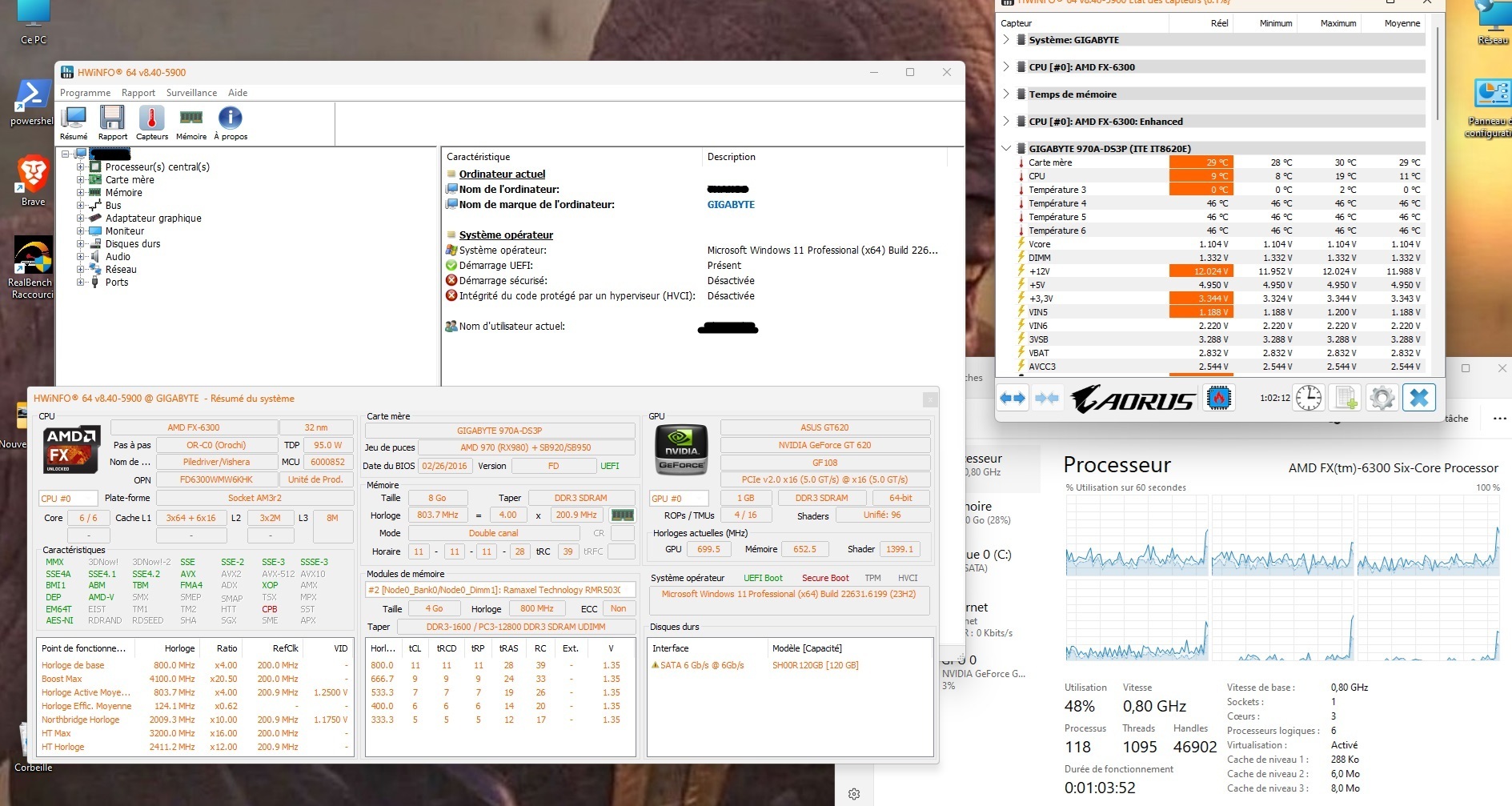 9°C on a desktop CPU in 2026. We were just shy of the dew point. It was beautiful.
Under load, it’s a different story
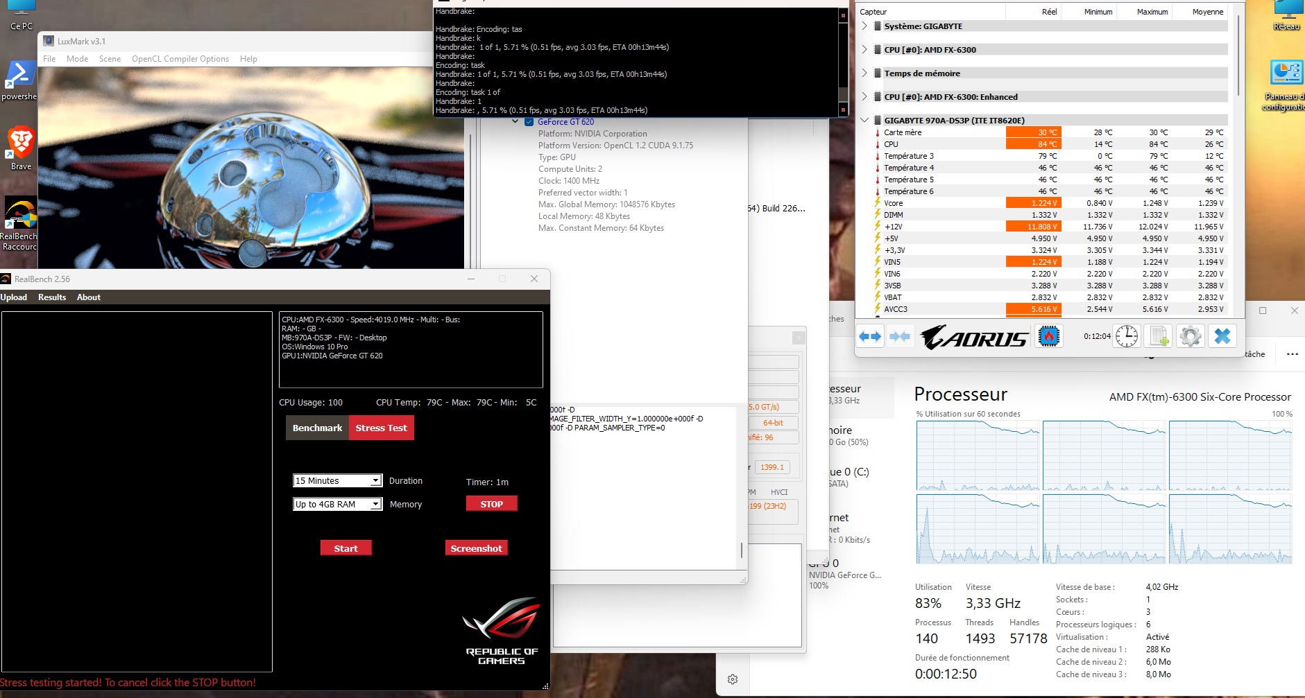 84°C and the CPU throttling on its own — 4.0GHz configured, 3.33GHz actual. Hotter AND slower than with air cooling alone.
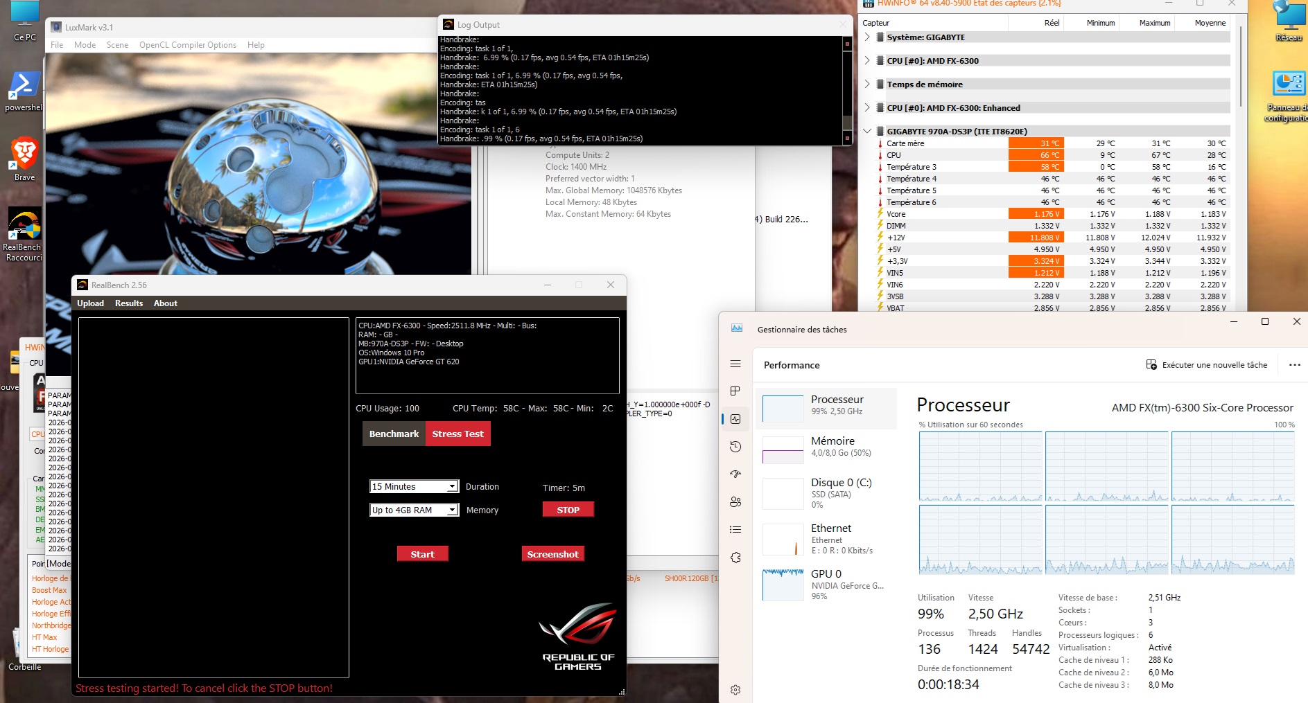 At 2.5GHz, 58°C under load — the only viable balance point in the entire test
Complete Table
| Frequency | Config | Idle | Max Load |
|---|---|---|---|
| 4.4 GHz | Air only (reference) | 35°C | 44°C ✅ |
| 4.4 GHz | + 1×90mm Peltier | 29°C | 89°C 💀 |
| 4.4 GHz | + 2×90mm Peltier | 29°C | crash 💀 |
| 4.4 GHz | + 3×90mm Peltier | 23°C | 85°C 💀 |
| 4.0 GHz | + 3×90mm Peltier | 14°C | 84°C 💀 + throttling |
| 3.5 GHz | + Peltier 3×90mm | 12°C | 85°C 💀 + throttling |
| 3.0 GHz | + Peltier 3×90mm | 11°C | 85°C 💀 + throttling |
| 2.5 GHz | + Peltier 3×90mm | 9°C | 58°C ✅ |
| 1.5 GHz | + Peltier 3×90mm | 9°C | — |
| 0.8 GHz | + Peltier 3×90mm | 9°C | — |
A detail visible in Task Manager: at 85°C and above, the CPU throttled on its own. At a configured 4.0 GHz, the Task Manager displayed an actual 3.33 GHz. The CPU overclocked with the Peltier module ran slower than with air cooling alone, while being twice as hot. The exact opposite of the intended goal.
Why it fails — the graphs that tell the whole story
The first graph shows the core problem: the red bar—60W from the Peltier—is **identical regardless of the CPU frequency**. The Peltier consumes 60W whether it has anything to cool or not. The heatsink’s capacity limit is exceeded as early as 2.5GHz.The second graph tells the whole story in a single image: the green curve (idle with Peltier) drops beautifully down to 9°C. The red curve (load with Peltier) shoots up to 85–89°C. The only viable equilibrium point: 2.5GHz, 58°C.
The conclusion everyone already knew
The Peltier doesn’t cool. It moves heat. And if you can’t dissipate that heat with an oversized heatsink—like a water block + car radiator or even a Vapochill for those who remember what that is—you’re making the situation worse instead of better.
That’s exactly why Peltier cooling for CPUs never caught on commercially. The few solutions that existed all used a compressor-based refrigeration circuit; the cell alone, without massive thermal infrastructure on the hot side, is a physical dead end.
Plus, the cost-benefit ratio is insane. A good €40 CPU cooler performs better, consumes less power, and won’t flood your socket with condensation.
Dozens of people have run this test before me with the same results. I knew it. I did it anyway.
And I don’t regret a thing.