I'm going to use this adapter, but those Molex connectors are driving me crazy… don't they?
What is that red wire?
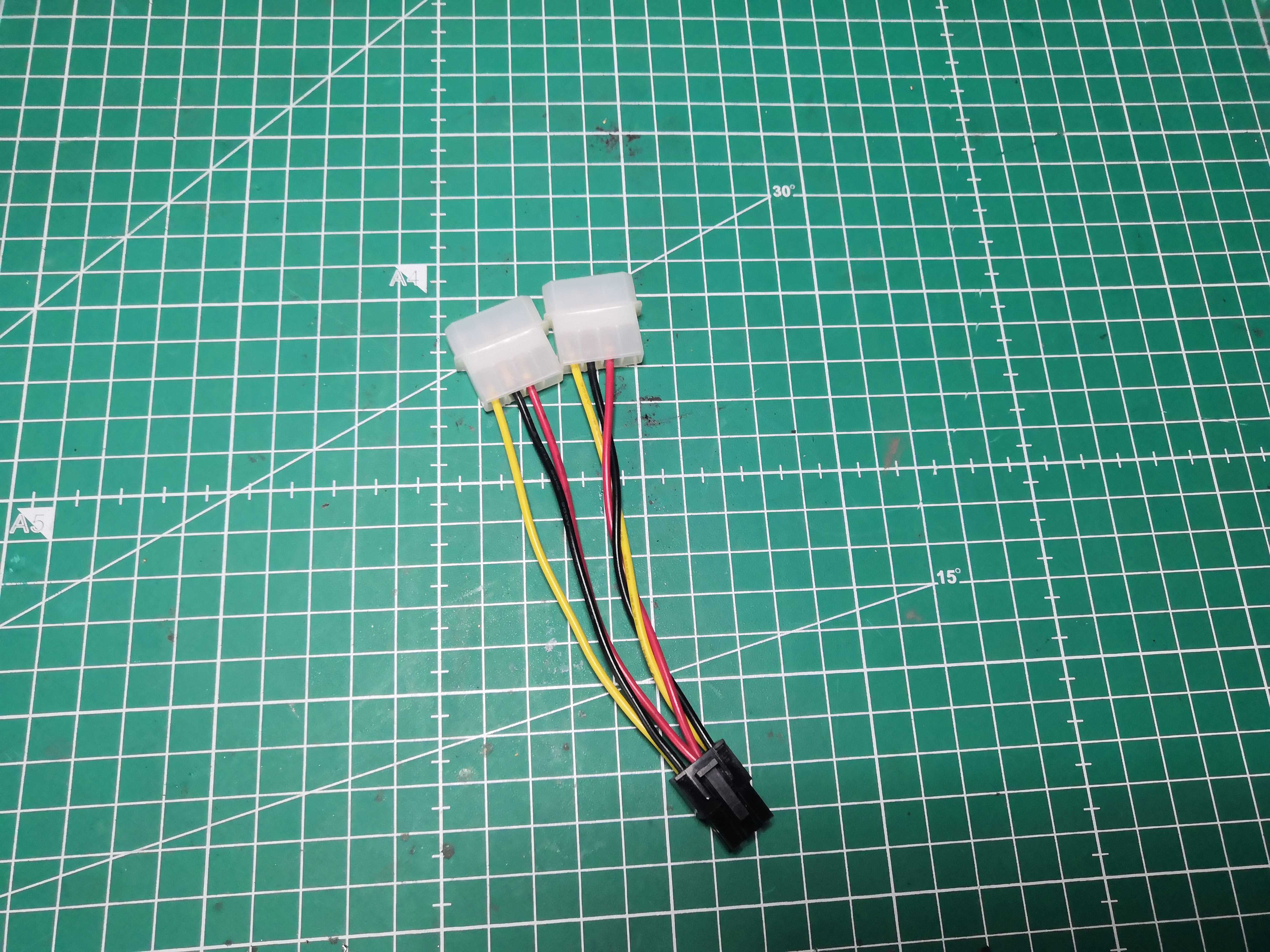 Two Molex connectors, one 6-pin PCIe connector, and that red wire hanging there. What is that thing?
My first thought upon seeing this adapter: "Red wire = +5V; it has no business being on a PCIe connector."
Except that’s not the case. That red wire isn’t +5V.
That’s exactly where it gets interesting—and dangerous if you assume instead of checking.
What the 6-pin PCIe connector really wants
The 6-pin PCIe is simple. Brutally simple.
┌──────────────────────────────┐
│  +12V       +12V      +12V   │  ← bottom row
│  GND        GND      Sense   │  ← top row
└──────────────────────────────┘
          [---------]        ← clip
+12V. Ground. A Sense line connected to ground to signal that the connector is present.
That’s it. No +5V. No +3.3V. Nothing else.
The actual wiring of our adapter — measured with a multimeter
Here’s what we actually have in front of us once we’ve pulled out the multimeter:
┌─────────────────────────────────┐
│  +12V         empty        +12V  │  ← bottom row (yellow - empty - yellow)
│  GND         2×Sense       GND  │  ← top row (black - 2 reds - black)
└─────────────────────────────────┘
             [---------]         ← clip
The two red wires soldered together on the center pin — that’s the Sense. Connected to ground, it tells the board that the 6-pin connector is present and active. Not +5V. It’s GND disguised as red to scare people.
The empty slot in the bottom row is the center position for +12V—this adapter only wires two out of three, which is more than enough for an RX 460 and its 75W TDP.
That’s exactly why we measure before making assumptions. A red wire could be +5V, Sense, GND, or something else depending on the cable’s origin. The color means nothing. The multimeter tells the whole story.
> Golden rule: never trust the colors. Measure before touching a soldering iron.
Our Wiring — Without Making a Mistake
On this adapter, it’s straightforward:
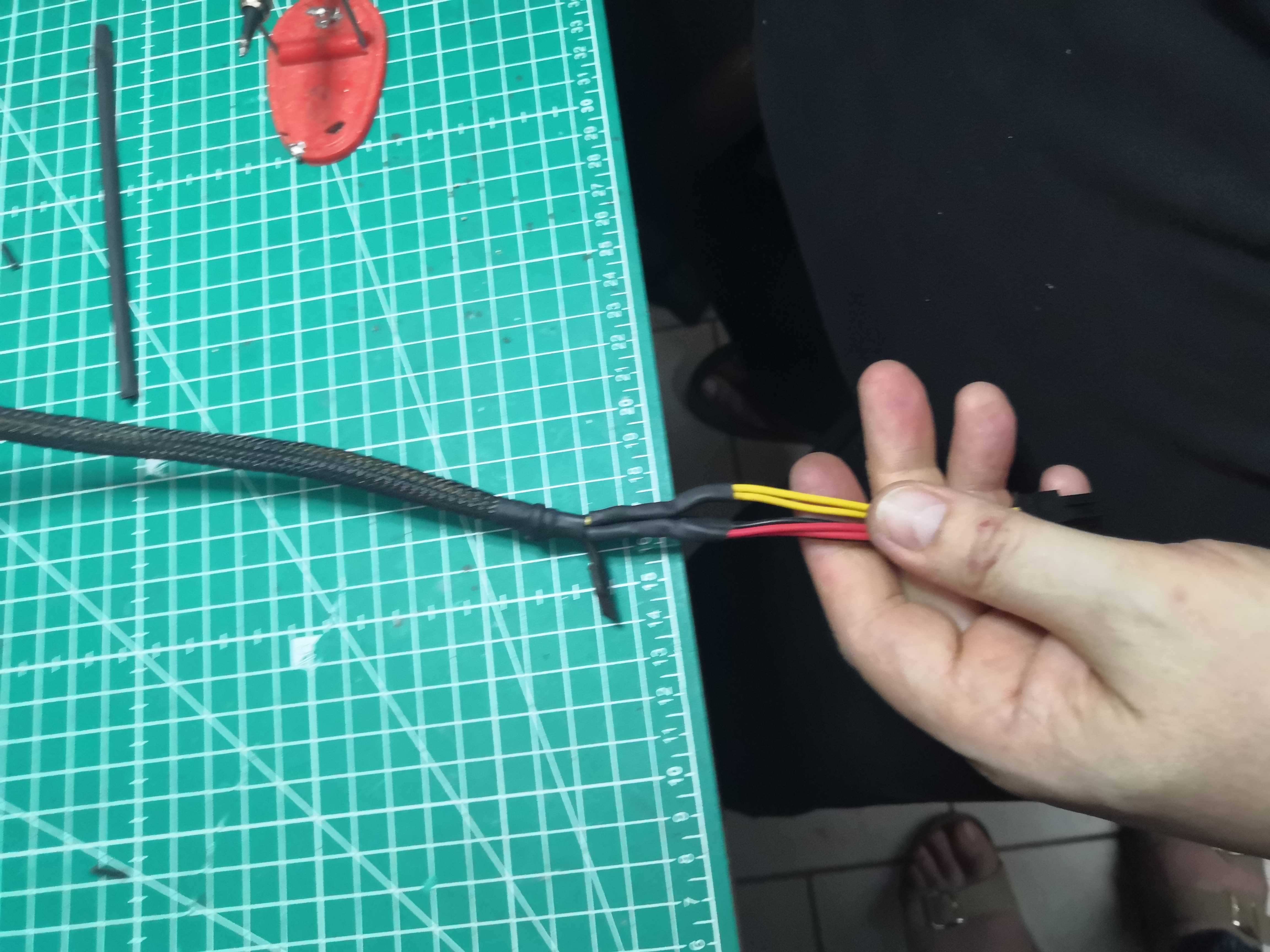
- Yellow → +12V from the 6-pin PCIe ✅
- Black → GND from the 6-pin PCIe ✅
- Red (×2) → Sense connected to ground ✅ — the board detects the connector, it boots up
We insulate the +5V source with heat shrink tubing. The wire is grounded, no residual voltage, no risk.
The logic is always the same: on a 6-pin PCIe connector, anything that isn’t +12V or GND must be connected to ground or isolated. Never left floating.
In all cases: multimeter first, soldering iron second.
The Build
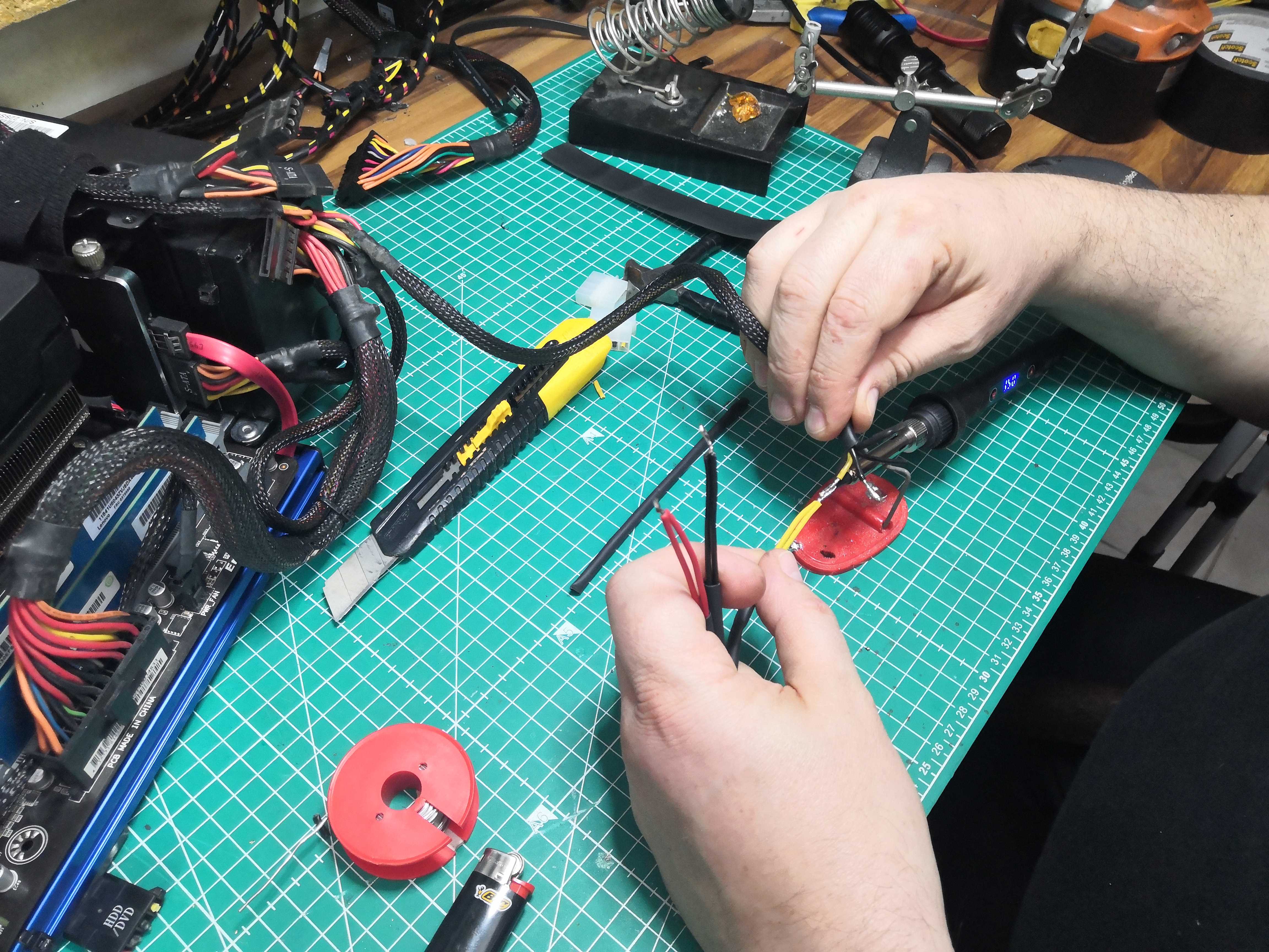
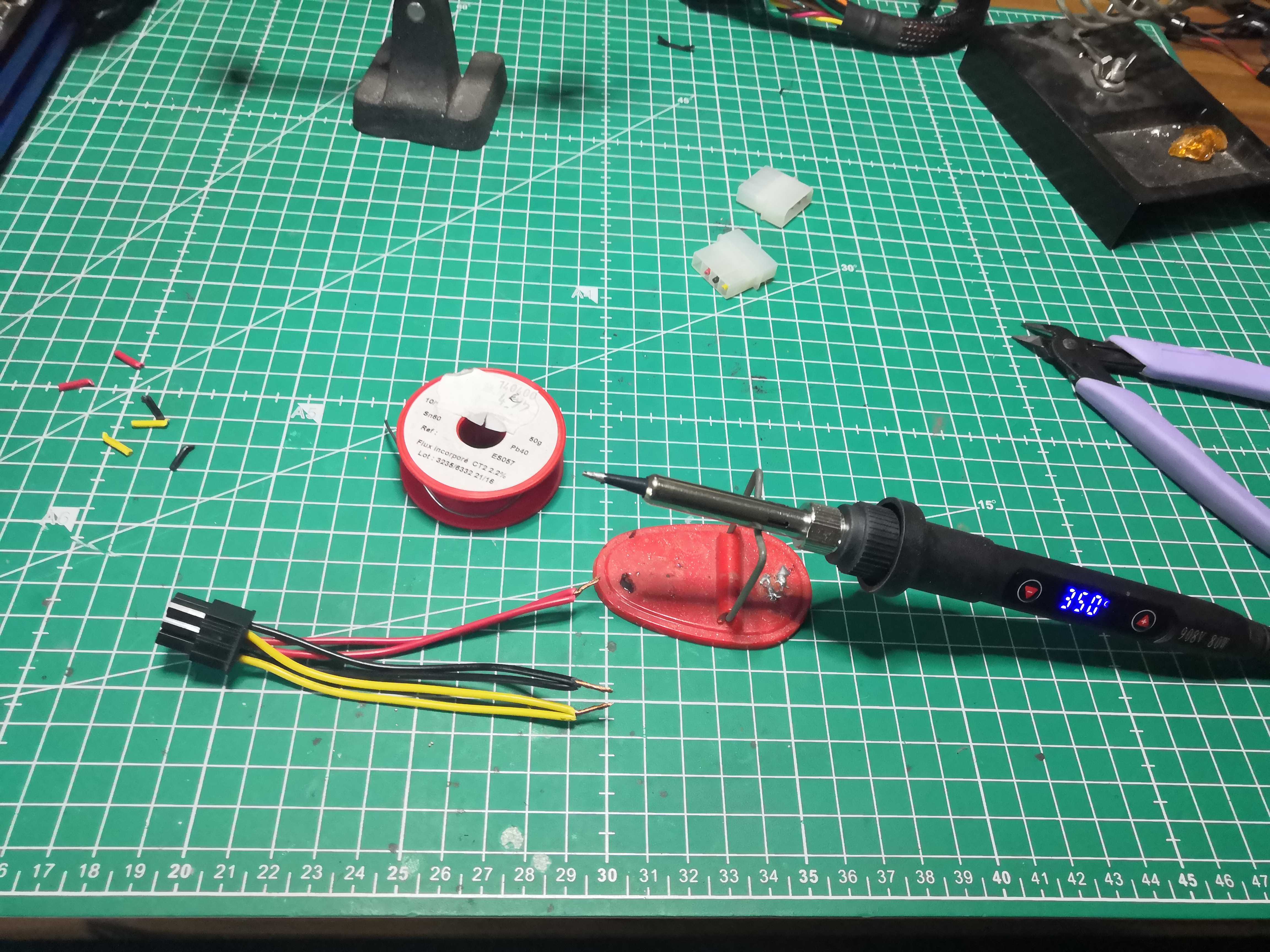 350°C, flux-cored solder, tubing in various diameters — the kit
 Each wire measured and identified before touching the soldering iron
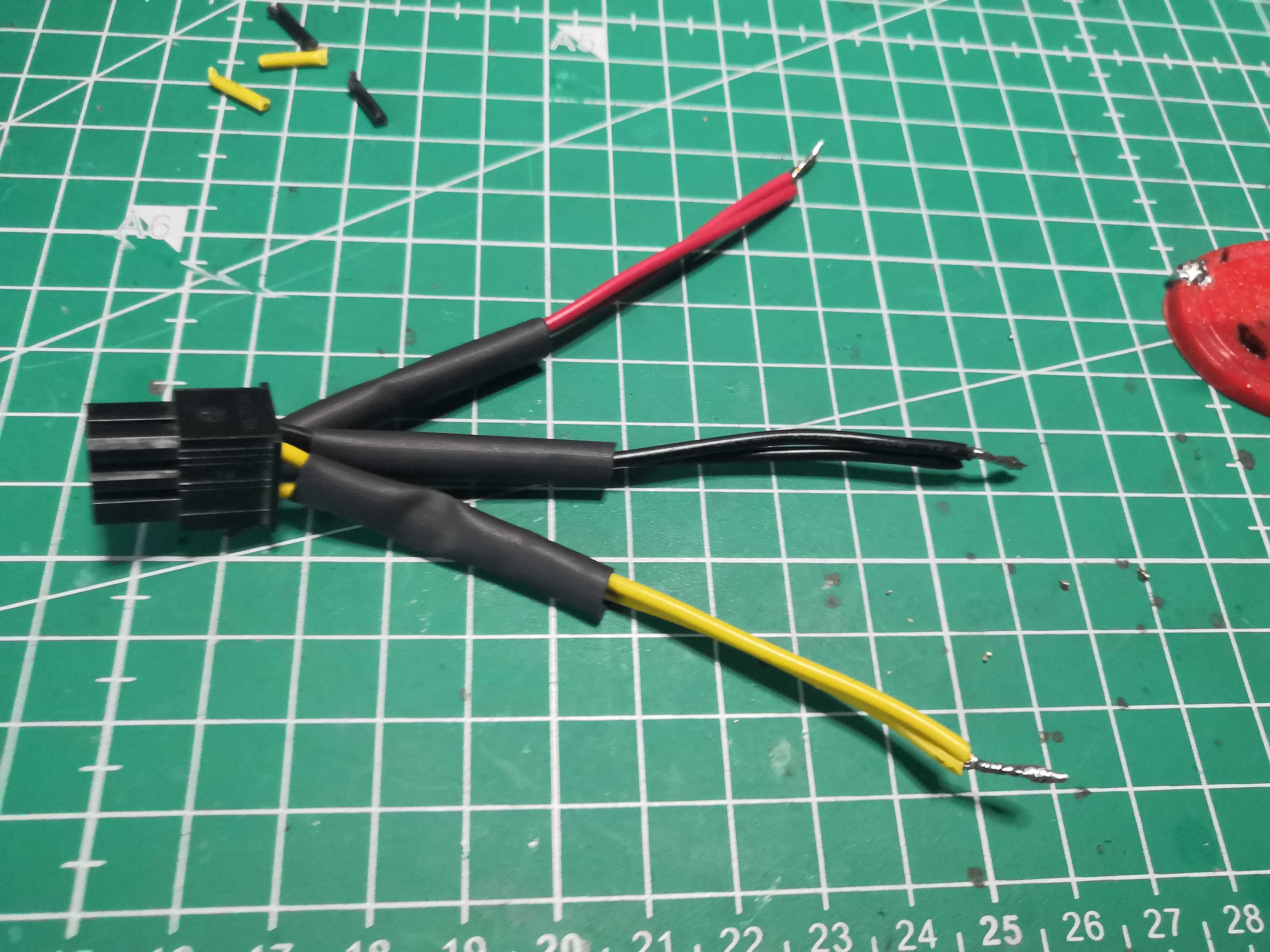
 One tube per solder joint, in order — don’t solder everything at once
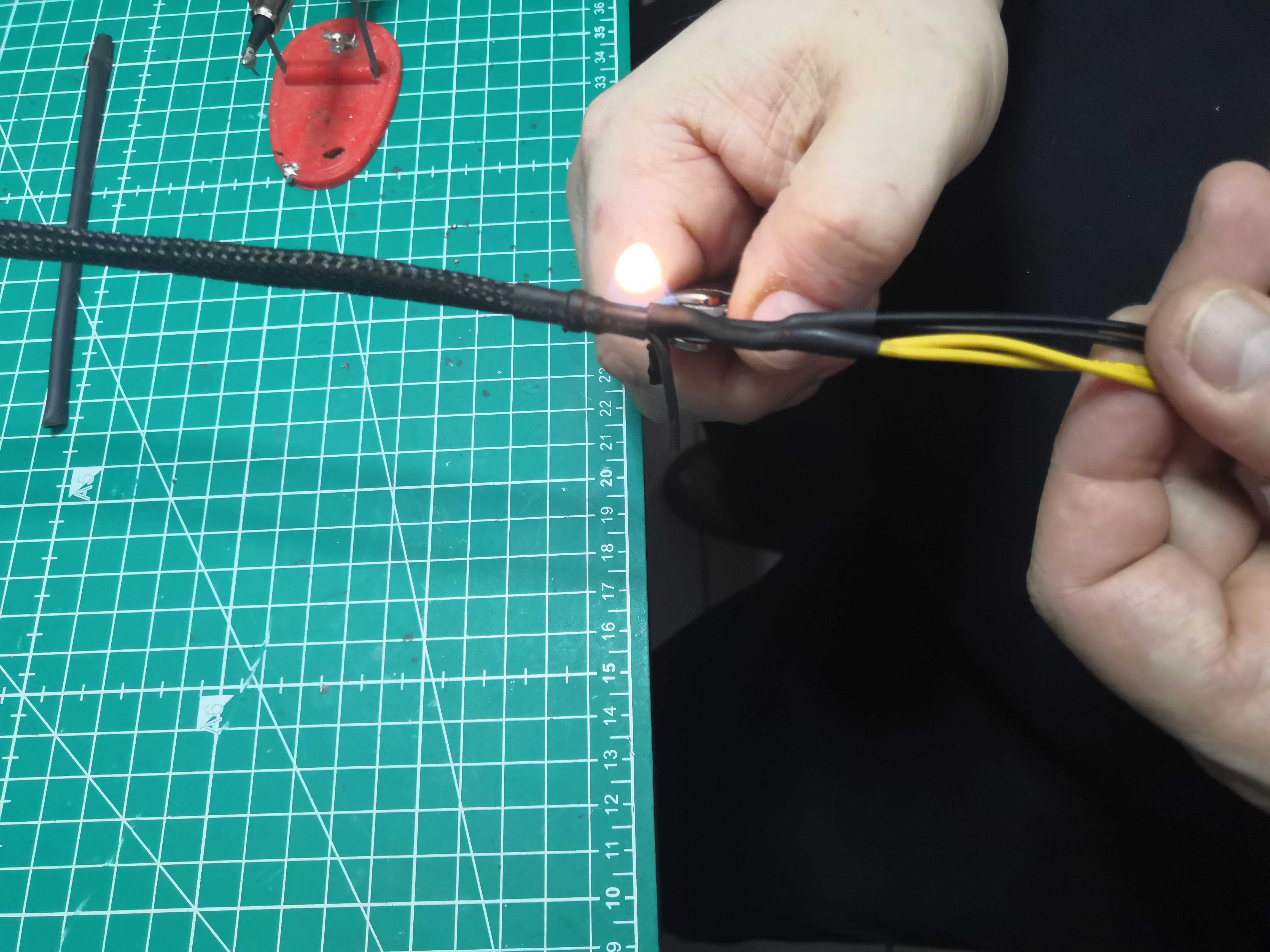 Lighter for large heat-shrink tubing — heat gun for small tubing if you have one
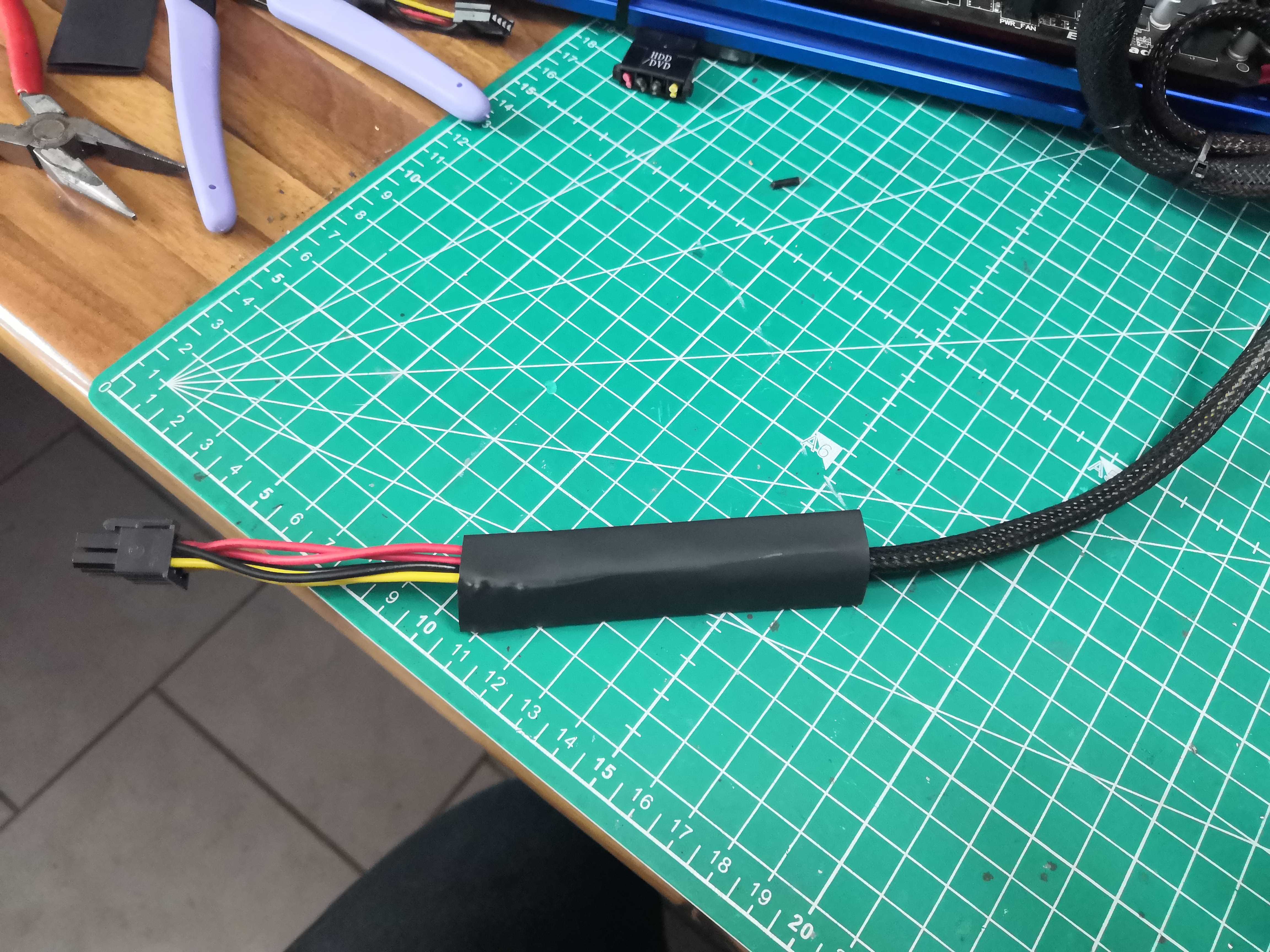
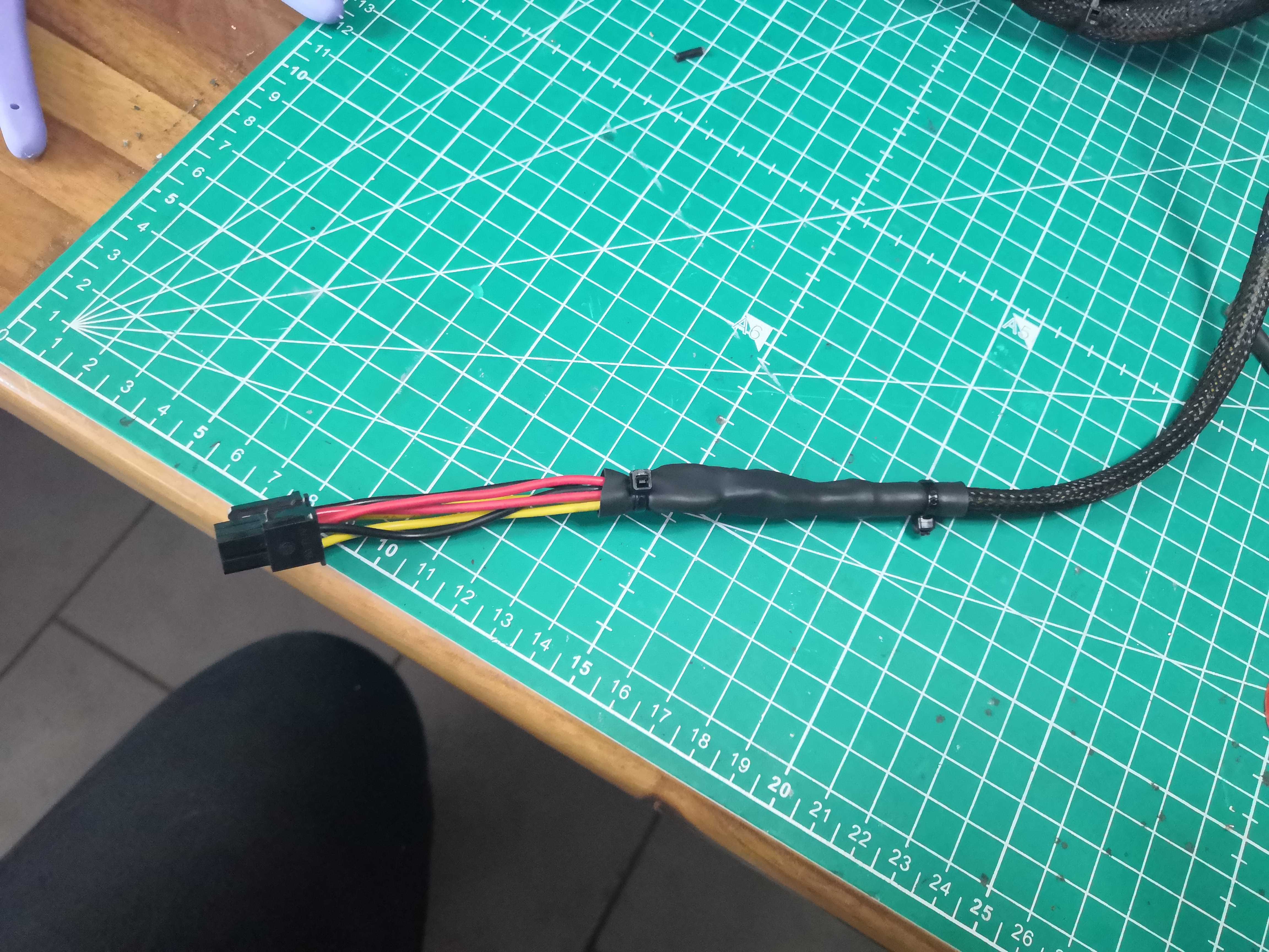 Cable ties on each side — if you pull on the cable, the heat-shrink tubing takes the strain, not the solder joint
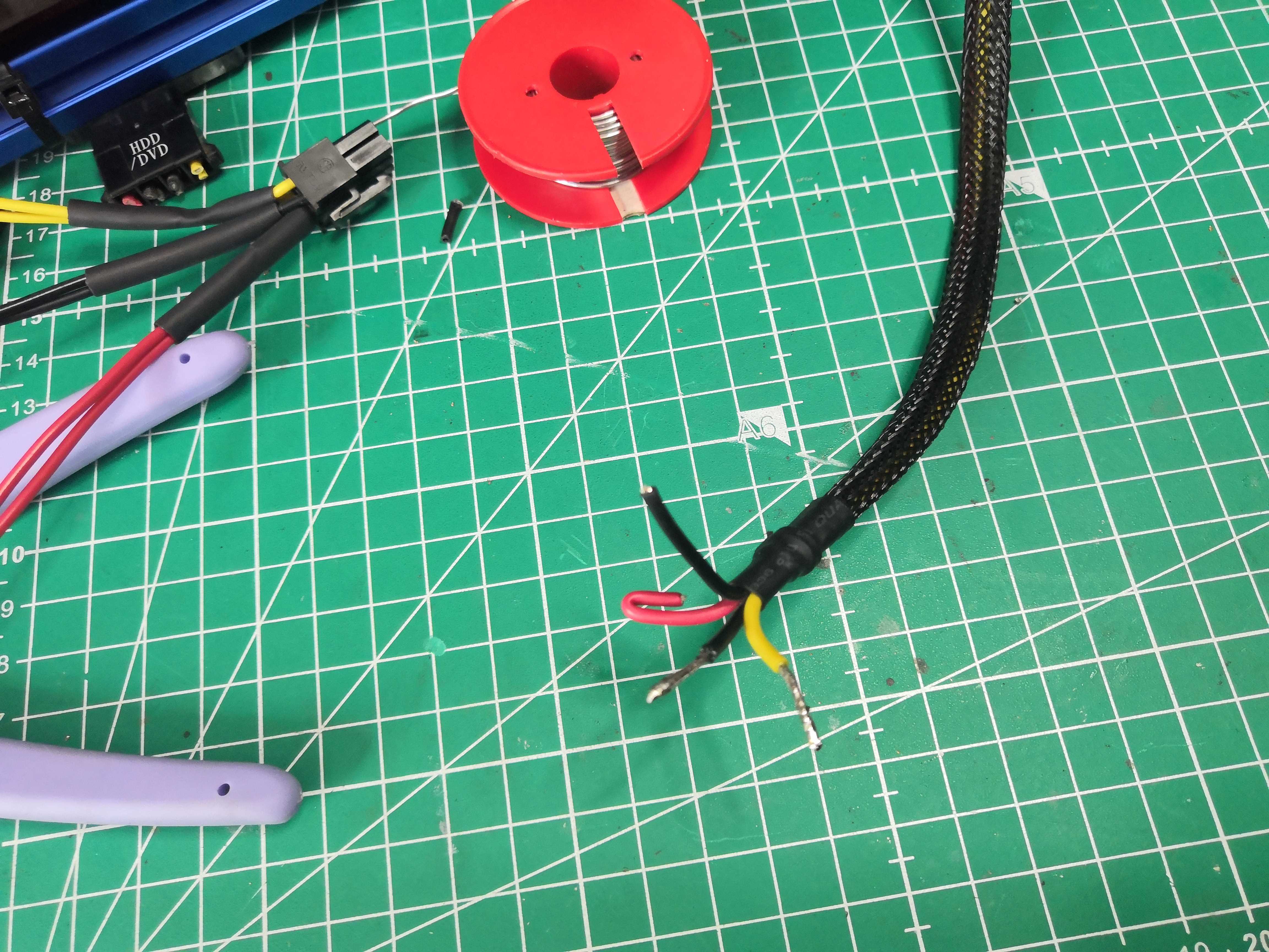
The result
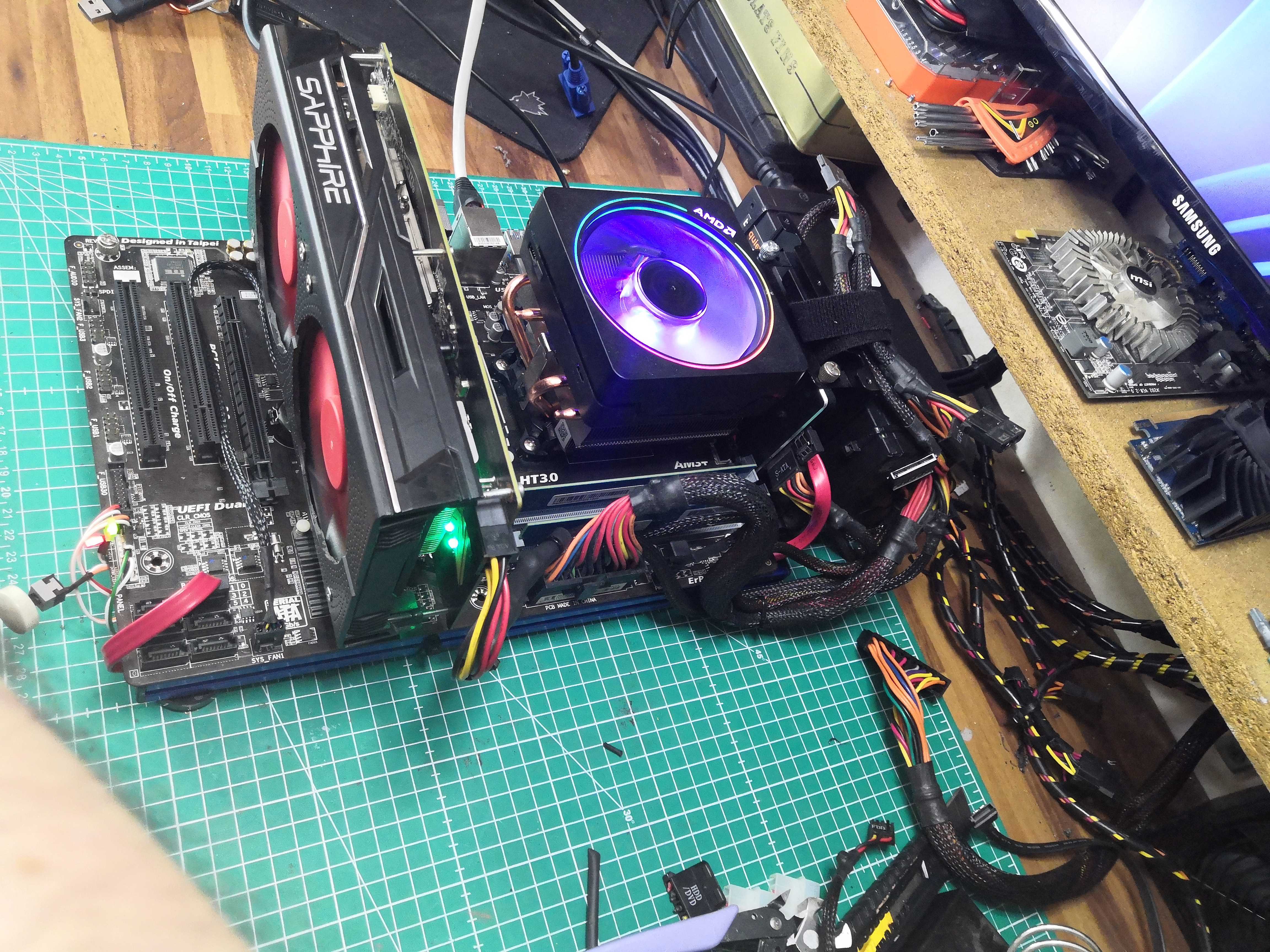 Powered up, booted, stable. No smoke lol.
The Sapphire NITRO RX 460 OC — whose cooling we redesigned in the previous article — is running properly. The cable is doing its job.